B2B Modular A Frame Home Exporter
- Cammi House
- 2026-10-20
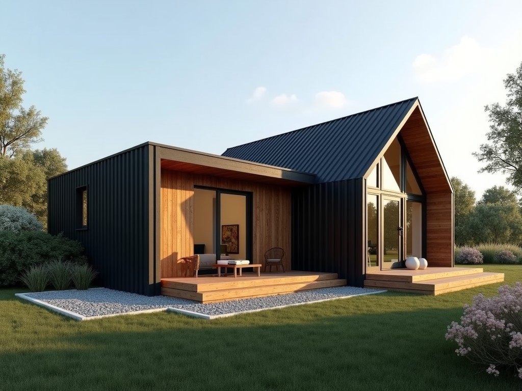
These prefabricated structures combine a steep 45° roof pitch with a rectangular footprint to shed snow and rain efficiently while providing high interior volume. Each module is engineered as a
Modular A-Frame Home Systems for B2B Export
Overview
These prefabricated structures combine a steep 45° roof pitch with a rectangular footprint to shed snow and rain efficiently while providing high interior volume. Each module is engineered as a self‑supporting unit that can be stacked or joined laterally to create multi‑room layouts without additional framing.
Standard module width is 2.4 m, length 3.0 m, and interior clear height 2.2 m at the sidewall, rising to 3.0 m at the ridge. The system is designed for flat‑bed container transport, with each module weighing approximately 1 200 kg when fully insulated and finished.
Structural Design
The primary load‑bearing frame consists of C‑section steel ribs spaced at 600 mm intervals, connected by galvanized gusset plates. Ribs are sized to resist a design snow load of 2.5 kN/m² and a basic wind pressure of 1.2 kN/m² (exposure C).
Shear walls are formed by oriented strand board (OSB) panels 18 mm thick, screwed to the ribs at 150 mm centers, providing lateral stiffness equivalent to a shear modulus of 2.8 GPa. Connections use M12 high‑strength bolts with torque‑controlled installation to ensure consistent preload.
Thermal and Acoustic Performance
Wall assemblies incorporate a 90 mm thick core of polyisocyanurate foam (λ = 0.022 W/m·K) between two 12 mm OSB skins, yielding an overall U‑value of 0.28 W/m²·K (R‑value ≈ 3.6 m²·K/W). Roof panels use the same foam core with an additional reflective foil layer, achieving a U‑value of 0.24 W/m²·K.
Acoustic insulation is provided by a 50 mm mineral wool layer (density 45 kg/m³) placed between the interior OSB and finish layer, resulting in a weighted sound reduction index (Rw) of 45 dB for typical traffic noise.
Typical Module Specifications
| Parameter | Typical Value | Notes |
|---|---|---|
| Module footprint | 2.4 m × 3.0 m | Rectangular base |
| Roof pitch | 45° | Optimized for snow shedding |
| Wall U‑value | 0.28 W/m²·K | Includes 90 mm PIR core |
| Snow load capacity | 2.5 kN/m² | Per EN 1991‑1‑3 |
| Wind pressure capacity | 1.2 kN/m² | Exposure C, gust factor 1.8 |
| Module weight (finished) | ≈ 1 200 kg | Includes insulation, finishes, fixtures |
Customization Options
- Exterior cladding: pre‑finished steel panels, fiber‑cement siding, or timber‑look composite boards.
- Interior finish: gypsum board with optional moisture‑resistant coating, or pre‑laminated PVC panels.
- Window and door configurations: operable casement, sliding, or bi‑fold units; sizes adjustable in 100 mm increments.
- Utility routing: pre‑drilled chases for electrical conduit, PEX plumbing, and HVAC ducts; can be sealed with fire‑rated mortar.
- Foundation compatibility: adjustable steel pier system, concrete pad, or screw‑pile adapters for rapid site installation.
Manufacturing and Quality Control
Modules are fabricated in a climate‑controlled facility using CNC‑cut steel ribs and automated panel lamination. Each joint undergoes torque verification with a calibrated wrench, and a random 10 % sample of panels is tested for thermal conductivity using a guarded hot‑plate apparatus (ASTM C518).
Dimensional tolerances are maintained within ±2 mm for panel thickness and ±3 mm for overall length/width, ensuring repeatable fit‑up during on‑site bolting. Final inspection includes a water‑spray test (EN 12208) to confirm joint sealing under a pressure of 0.3 kPa.
Packaging and Export Logistics
Finished modules are wrapped in UV‑stabilized polyethylene shrink film, then placed on steel pallets equipped with forklift pockets. Each pallet is fitted with corner protectors and steel strapping to resist shifting during transit. A standard 40‑foot high‑cube container accommodates up to six modules, depending on optional accessories.
Export documentation includes a detailed bill of materials, material safety data sheets for insulation, and a structural calculation package signed by a licensed civil engineer. These documents facilitate customs clearance and reduce on‑site engineering review time.
Applications in Industrial and Commercial Sectors
The steep roof geometry provides excellent runoff for facilities located in high‑precipitation zones, reducing the risk of water ingress on stored goods. Because the structural system carries loads primarily through the frame, interior columns can be minimized, offering clear spans suitable for warehousing, equipment shelters, or temporary office complexes.
Modules can be rapidly deployed as expandable housing for remote project crews, with the ability to add sanitary cores and HVAC units as separate, plug‑and‑play units. The factory‑finished exterior reduces on‑site painting time, lowering overall project schedule by an estimated 20 % compared with conventional stick‑built alternatives.
Frequently Asked Questions
- Can dimensions be customized? Yes, module length and width can be adjusted in 100 mm increments while maintaining the 45° roof pitch; structural re‑analysis is provided for each variant.
- What information is required before quotation? Site plan, intended use, required interior finishes, and any specific load cases (e.g., equipment loads, seismic zone).
- What materials are available for the structural frame? Standard is hot‑dip galvanized S355 steel; optional stainless steel (grade 304) or weathering steel (Corten) can be supplied upon request.
- How is quality inspected? Incoming steel is checked for coating thickness (ISO 1461); panel bonding is verified by peel strength test (ASTM D903); final assembly undergoes torque audit and water‑spray test.
- What packaging methods are available? Standard is shrink‑wrapped pallets; optional container‑frame cradles for fragile finishes or additional corner reinforcement for rough handling.
- How are export shipments protected? Modules are secured with lashing to container lugs, and desiccant bags are placed inside the wrapping to control moisture during transit.
- What is the typical production lead time? Six to eight weeks after receipt of final design approval and deposit, subject to current workshop capacity.
- How are samples arranged? A scaled 1:10 structural sample can be shipped via air freight for connection evaluation; full‑size module samples are available for pickup at the factory.
Next Steps
To obtain a detailed technical proposal, please provide your project specifications, desired configuration, and delivery destination. Our engineering team will return a comprehensive package including load calculations, fabrication drawings, and a firm delivery schedule.
Request a Technical Quote